Output devices
Table of content:
1 - Exploring output devices1.1 - Led and buzzer
1.2 - LCD
1.3 - oled
1.3.1 - oled text 1.3.2 - oled image 1.3.3 - oled animation 1.3.4 - oled aniation v2
1.4 - 7 segment display
1.5 - Servo
1.6 - stepper
2 - Designing the Output board
3 - Milling the Output board
4 - Programming the Output board
4.1 - oled 4.2 - LCD 4.3 - 7 segment
5- Group assignment
Exploring output devices
In this week of Output devices, I explored a few component that comes under output devices. I initially tried them onto the Arduino UNO
board with Arduino language because the wiring is easy, you don't need to solder anything and you can quickly re-wire if there is any mistake
and the Arduino language is easy to understand and also you'll find a lot of tutorials online of how to operate a specific output device with
Arduino. In my final project of detecting water leakage, I would require something to give feedback if the leakage is detected. For the instant
feedback I can use buzzer and led, for giving feedback in the form of data, i can use a LCD or OLED display. So in this week, apart from
LED's(which I have already explored while making hello world board), buzzer, LCD and OLED, I explored few others output components, more on
that later.
LED and Buzzer
For buzzer and LED, I used digitalWrite for the buzzer which is either HIGH or LOW(on or off)
and for the LED i used analogWrite where you can set the brightness between 0 and 255 where 0 is
lowest brightness and 255 is highest brightness. For using the analogWrite command you'll need
to use PWM pins(pin number 3, 5, 6, 9, 10, 11), the one indicicated by the symbol "~" onto the arduino board.
<<<---WIRING--->>>
For the buzzer, i attached the anode pin onto digitalpin 8 and cathode pin to the ground.
for thr LED, i attached the anode pin onto digitalpin 3 and cathode pin to the ground.
(to identify which pin is anode or cathode look at the size of the pins, anode pin will alwayes be longer than the cathode pin.)
<<<---CODE--->>>
This is the code i used for programming,
you can copy the code from here too.
In the first two lines, i defined the pin number of the LED and buzzer. In the void setup() { i defind whether the LED pin and
buazzer pin are input or output. In the void loop() { , with the help of digitalWrite i turned the buzzer on and then
turned if off. In between turning the buzzer on and off, with the help of analogWrite, i turined the LED on from lowest brightness
to the highest brightness and then back to the lowest brightness. At the end i gave the delay of 2 seconds(2000 milisecond)
<<<---OUTCOME--->>>
Here is the results after uploading the code to the Arduino UNO,
LCD - Liquid Crystal Display
I am using the 16x2 character LCD. To operate the LCD, one can connect the LCD with the Arduino in two ways. One way is to directly connect the LCD with the Arduino which would
require 16 pins and that would be very messy. Another way is to connect the LCD with the I2C module then connect the I2C module with Arduino
which would require 4 pins.
<<<---WIRING--->>>
In the I2C module, you will observe a single pin surrounded by a box. You need to attach the I2C with the LCD in the orientation where the box
pin is connected with the pin1(VSS) of the LCD. Now connect the GND and VCC of I2C with GND and VCC of Arduino and connect the SDA and SCL of the
I2C with A4 and A5 of the Arduino respectively. SDA and SCL are assigned to the specific pins of any IC, you cannot use any other pins. For
better understanding of wiring refer to https://lastminuteengineers.b-cdn.net/wp-content/uploads/arduino/I2C-LCD-Display-Pinout.png. This is a
website where you'll find a lot of information regardiing how to connect and run multiple devices with arduino:
https://lastminuteengineers.com/
<<<---CODE--->>>
This is the code I used for programming,
you can copy the code from here too.
Source of the sketch i used: https://github.com/futureshocked/ArduinoSbS2017/blob/master/_0710_-_LCD_I2C/_0710_-_LCD_I2C.ino
I installed this library called "LiquidCrystal I2C" by Marco Schwartz from sketch > libraries > manage libraries.
There is a line in the sketch LiquidCrystal_I2C lcd(0x27,16,2); where 0x27 is the hexadecimal address of the I2C device. Each
I2C device has different Hexadecimal Address and to find that you need to upload the below sketch while your I2C is connnected in your system
and after the sketch is uploaded, you'll find the I2C address in the serial monitor,
you can copy the code from here too.
Source of the sketch I used for finding hexadecimal address of the i2c: https://www.instructables.com/OLED-I2C-DISPLAY-WITH-ARDUINO-Tutorial/
In the void setup() there is a line lcd.setCursor(4, 0); which is setting the row and column number where you want to
start displaying. lcd.setCursor(x, y); where y means is on which row you want to display the text, 0 means first row and 1 means
second row. x means on which column you want to start displaying the text, 0 means first column and so on.
<<<---OUTCOME--->>>
You can see me tweaking the x and y value to change the alignment of the texts.
OLED display - Organic Light Emitting Diode display
I was using the 0.96 inch OLED display. OLED is quite similar to the 16x2 character LCD display. Unlike the LCD you don't need a separate I2C
module to operate the OLED. OLED works on pixels so apart from text, you can do a lot of other creative stuff like form an image and you can
also form animations on the OLED.
<<<---WIRING--->>>
There are four pins onthe OLED display. Connect the GND and VCC of the OLED display with the GND and VCC of the UNO. Connect the SCK/SCL pin of
the OLED with Analog pin A5 and connect SDA pin of the OLED with the analog pin A4 of the Arduino UNO.
OLED Text
<<<---CODE--->>>
This is the code is used for displaying the text on the OELD,
you can copy the code from here too.
Reference link for the OLED text: https://www.youtube.com/watch?v=_KD7skmusTQ
You'll meed to first install these libraries from sketch > include libraries > Manage Libraries,
- Adafruit GFX library by Adafruit
- Adafruit SSD1306 by Adafruit
Just like the LCD, you'll first need to find hexadecimal address of you OLED by uploading the I2C finder code to your UNO while your OLED is
connected. You'll find the code above. display.begin(SSD1306_SWITCHCAPVCC, 0X3C); replace the 0x3C with the hexadecimal address
you find in the serial monitor.
In the void loop() { there is a line display.setTextSize(1); where you need to set the size of the text. When i was
testing, i was only able to set the size as a whole number like 1, 2, 3 and not 0.5.
Just like in the LCD there is display.setCursor(0,0); where uou can set the row and column number where you want to start displaying
the text. display.setCursor(x, y); where y means is on which row you want to display the text, 0 means first row, 1 means
second row and so on. x means on which column you want to start displaying the text, 0 means first column and so on.
<<<---OUTCOME--->>>
OLED Image
To show an image onto the OLED, we will take and image and convert it into bitmap and upload it to the Arduino UNO.
<<<---CODE--->>>
This is the code i used for displaying an image onto the OLED,
you can copy the code from here too.
To show an image into the OLED, you need to to convert the image into the bitmap. The bunch of hexadecimal numbers(0xff) that you are seeing
are the bitmap of the image.
Below is the blank sketch for you to paste the bitmap,
you can copy the code from here too.
Converting an image to bitmap
For testing i was using black and white icons, without a lot of details. You can download free icons from website like: https://iconarchive.com/
AFter sellecting the image, go to this website: https://javl.github.io/image2cpp/
and follow these steps to convert your image into bitmap,
- under "select image" tab upload the image which you want to convert into bitmap.
- under the "image settings" tab set the canvas size to 128x32 pixels
- For scaling select "scale to fit, keeping proportions"
- select "horizantally" for the Center
- tweak the Brightness/alpha threshold by looking at the preview until you get the desired results.
- under "Output" tab select Arduino code
- click on "Generate code" and it will generate the bitmap of your image.
- copy the whole set of hexadecimal number and paste it just before the void setup() {
- YOu can copy the const unsigned char myBitmap [] PROGMEM = { too from the generated code ,but make sure the word after
char and before [] in the line const unsigned char frame0 [] PROGMEM = { in the void setup () {
and the word after 0, 0 in the line display.drawBitmap(0, 0, myBitmap, 128, 64, WHITE); in the void loop
() {}
are same
<<<---OUTCOME--->>>
Reference link: https://www.youtube.com/watch?v=kSRytu8Q0Vo
OLED Animation
TO display an image into the OLED we were taking an image and converting into bitmap. In the animation, we will take a GIF file and split that
GIF file into frames. Then convert each frame into bitmap format and upload the array of bitmap into the Arduino UNO.
<<<---CODE--->>>
This is the code i used for displaying an animation onto the OLED,
you can copy the code from here too.
follow these steps to display an animation into your OLED,
- download a GIF file or an animated icon. You'll find some free animated icons from here: https://icons8.com/free-animated-icons
- split that GIF into frames. There is a website where you can split a GIF into frames online: https://ezgif.com/split . You can download a zip
file of all the frames after the GIF is split into frames.
- convert every frames of the GIF(which will be in .gif format) into bitmap. For that i used xnconvert software to convert images in .gif
format to images in .bmp format. While converting into .bmp format make sure you set 32x32 pixels while converting the file, in xnconvert you
can set the size under "Actions" tab. After that open the OLEDAnimations software and click on "select folder" and give the path where you have
exported the .bmp files. Link for downloading OLEDAnimations: https://drive.google.com/open?id=1ECufN2p8tpTUwq2UFgZK_Rq3wDmOACDo
After selecting the path you'll get the bitmap for all the images. Click on "Copy to clipboard" on the left side with bunch of hexadecimal numbers
and pate it above void setup() { (you'll find a blank sketch above to paste the bitmap). On the right, click on "Copy to clipboard"
and paste it in the void loop () { and uplaod the code.
You'll find the blank sketch for oled animation here:
you can copy the code from here too.
This is the reference link from where i learned how to do animation in OLED: https://www.youtube.com/watch?v=0KGMFhFQ0YY
He followed the similar steps that i have mentioned and he got the expected results while i was not able to display the animation properly. You'll
see that in the first 2 minutes 23 seconds of the video,
<<<---OUTCOME--->>>
So i then tried to display the animation in a different way which is similar to displaying the image, however quite tideous.
OLED Animation v2
<<<---CODE--->>>
This is the code i used for displaying the same animation with another way,
you can copy the code from here too.
I followed this steps,
- Download any GIF file and split it into frames, you'll find the steps in detail above.
- open this website: https://javl.github.io/image2cpp/ and upload all the frame that are in .gif format.
- set the canvas size 128x32 pixel under "Image settings" You don't need to change the size of every image one by one manually, just scroll
down and click on "all same size"
- For scaling select "scale to fit, keeping proportions"
- select "horizantally" for the Center
- tweak the Brightness/alpha threshold by looking at the preview until you get the desired results.
- under "Output" tab select Arduino code
- click on "Generate code" and it will generate the bitmap of all the frames.
- Replace/paste all the hexadecimal numbers above void setup () {
- as mentioned above, make sure the word after
char and before [] in the line const unsigned char frame0 [] PROGMEM = { in the void setup () {
and the word after 0, 0 in the line display.drawBitmap(0, 0, myBitmap, 128, 64, WHITE); in the void loop
() {}
are same
so you need to make changes in the sketch accordingly.
- lastly, replace 32, 32 with 128, 32 in all the lines like display.drawBitmap(xx, yy,frame27,128,32, 1); in the void loop
() {
<<<---OUTCOME--->>>
Here is the result,
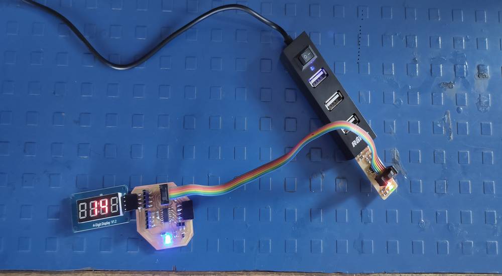
7 segment display & Arduino UNO
The 7 segment display i was using was 4 digit display with 7 segment for each digit. You need to activate each segment with the help of array
in order to display the
digit you desired. You will get a better idea looking at this GIF, :https://lastminuteengineers.b-cdn.net/wp-content/uploads/arduino/Common-Cathode-7-Segment-Display-Internal-Working.gif
Using a kibrary you can easily display any digit, you can download the library from Sketch > include library > manage libraries and install
the ‘tm1637‘ library by Avishay Orpaz.
<<<---WIRING--->>>
There are 4 pins on the 7 segment display, Ground - VCC - CLock input(CLK) - Data input ouput(DIO). Connect the GND and VCC of the 7 segment
with the GND and VCC of the Arduino UNO and connect the CLK and DIO to any digital pins of the UNO. You just need to define the CLK and DIO
pin in your sketch.
<<<---CODE--->>>
You can get an example sketch from File > examples > TM1637 > TM1637test, which is very similar to the sketch i used for testing. Refernce link
of the website from where i learned how to operate 7 segment and the sketch: https://lastminuteengineers.com/tm1637-arduino-tutorial/
and this is the code i used,
you can copy the code from here too.
FIrst i included a the library and then i defined the CLK and DIO pin.
There are bunch of arrays before void setup () { where each segment is declared for each digit. Looking at that and the image(link
i shared above) i wrote an array for the dash on all 4 digit.
In the void setup () { you can set the brightness of the display and i have declared to initally turn off the display after displaying
dash on all 4 digit.
There is a line in void loop () { like display.showNumberDec(14, false, 2, 1); where 14 means the number you want to
display in the 7 segment. false means only the digits 14 will display, if you write true instead, 0014 will display in the 7 segment. 2 means
digit count, 14 has 2 digits, 0014 has 4 digits and so on. 1 means the starting position of the display, where 0 means 14--, 1 means -14-
2 means --14 and so on.
In the line display.setSegments(done); you can call the array that you have defined above.
<<<---OUTCOME--->>>
You'll see me tweaking bunch of lines in the sketch with bunch of different outcomes,
Servo
I was using SG-90 servo motor with plastic gears whichcan rotate 90° on both direction. The one good thing about servo motor is unlike stepper
motor, servo motor remember its shaft's position.
<<<---WIRING--->>>
There are 3 pins on the servo motor, GND - VCC - DATA pin. Connect the GND and VCC pin of the servo to the GND and VCC of the UNO and connect
the data pin of the servo to any digital pin of the UNO. You just need to declare the data pin into your sketch.
<<<---CODE--->>>
This is the code i used for testing the servo,
you can copy the code from here too.
You can get this sketch from file > example > servo > sweep.
Before the void setup () { there is a line int pos = 0; where 0 is setting the position of the servo to 0° when the
UNO is powered up or reset.
In the void loop () { there is a line for (pos = 0; pos <= 180; pos += 1) { where it is telling the motor to rotate
from 0° to 180° with 1° increment for every step, every 15 milisecond. And then back to 0° from 180°. SO from 0° to 180° it is 0° to less than
or equal to 180° with increment of 1°(+) and from 180° to 0° it is 180° to more than or equal to 0° with decrement of 1°(-).
You can see me changing the rotation from anticlockwise (0° to 180°) to clockwise (180° to 0°) by changing this
line for (pos = 0; pos <= 180; pos += 1) {. I actually should have interchanged both the lines rather than editing both line one
by one.
if you want your servo to start from a particular degree position it is better to write that degree in this line myservo.write(90);
in void setup () { rather than in void loop () { because the void loop will consider that initial position in every
cycle.
<<<---OUTCOME--->>>
You can see all the outcome after tweaking bunch of lines in the sketch,
Stepper motor & A3967 easy driver
I used the NEMA 17 stepper motor and the A3967 easy driver to run the stepper motor.
<<<---WIRING--->>>
You can operate the stepper with just 4 pins, 2 for power supply and other 2 for step and direction(any 2 digitial pin) and even i used that 4
pins to rotate the stepper motor, however I did considered wiring the other 3 pins, MS1 - MS2 - EN but didn't use them. You can see the
schematic for wiring here: https://cdn.sparkfun.com/assets/learn_tutorials/2/4/1/EasyDriverHookup_bb2.png .
Source of the schematic: https://learn.sparkfun.com/tutorials/easy-driver-hook-up-guide/all
<<<---CODE--->>>
This is the code i used to operate the stepper motor,
you can copy the code from here too.
Source of the code(The 101): https://www.norwegiancreations.com/2014/12/arduino-tutorial-stepper-motor-with-easydriver/
In the first few line i defined the direction(dir), step(stp), ms1, ms2 and enable pin and in the void setup () { i declared the stp
and dir pin as output.
The 360° in the stepper motor is divided into 1600 steps. So in the void loop () { there is a line
for (int i = 0; i < 1600; i++){ where it is telling the motor to rotate 1600 steps and the line
delayMicroseconds(100); is telling the motor to rotate 1600 steps WITHIN 100 miliseconds, which is wuite opposite compared to
the servo when the miliseconds mentioned in the sketch is the delay between each step/degree.
In the line digitalWrite(dir, HIGH); direction HIGH was anticlockwise for me.
<<<---OUTCOME--->>>
You can see me changing the direcrtion, number of steps and the delay to rotate the motor back and forth continuously in loop,
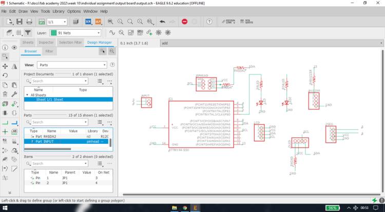
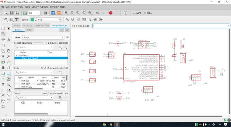
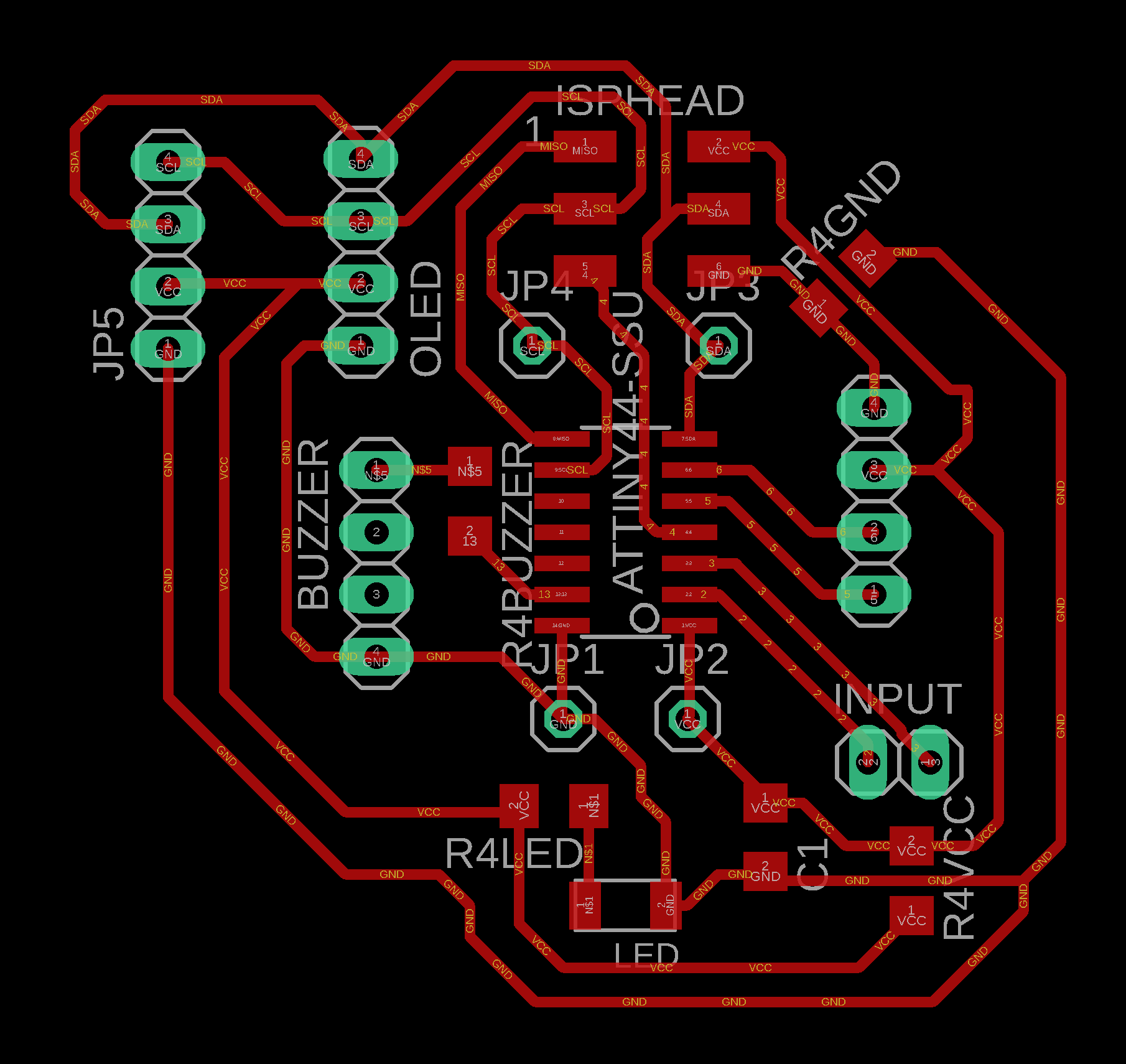
Designing the Output board
I intended to use LED which will turn on when plugged in with the programmer and so it will act as one of the output device. I then planned
to give provision for buzzer, OLED, LCD, 7 segment and 2 pin for input device(future use). I started adding the parts in the schematic file
and this is the schematic i ended up with,
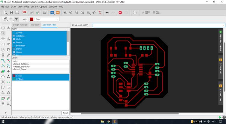
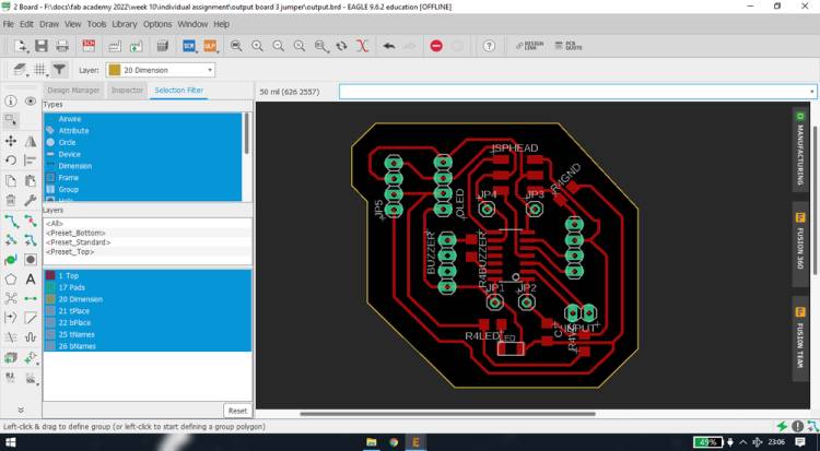
I was not able to route the board without adding 3x 0ohms resistor that were acting as a resistor. This is the how I routed the board,
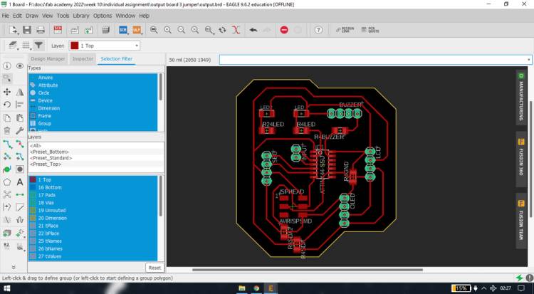
In the "fab" library, there were only 2x2, 2x3 & 2x5 SMD pin header. So to add 1x2 and 1x4 SMD pin header i use the "pinhead" library which was
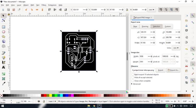
pre-installed in the eagle. Now these pin header had a small hole in the middle which i thought that the machine would cut while tarcing, so
i filled them with white color in inkscape,
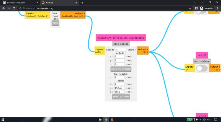
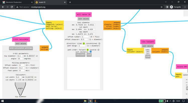
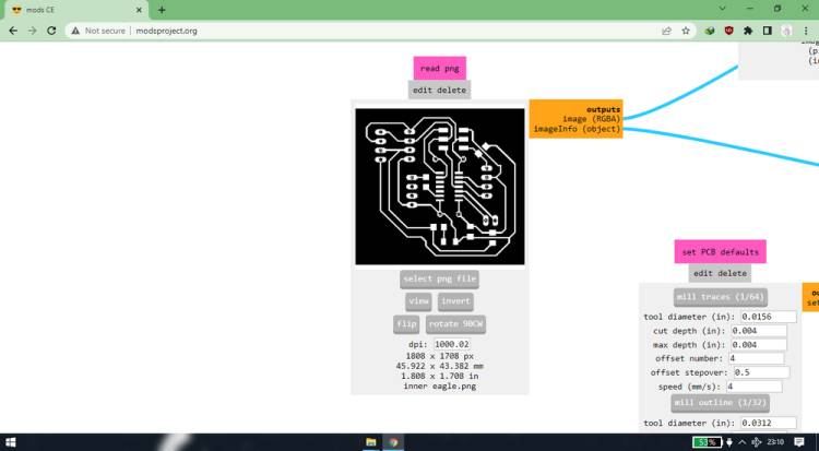
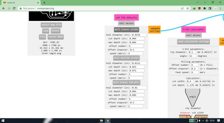
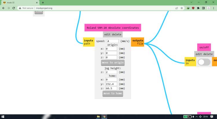
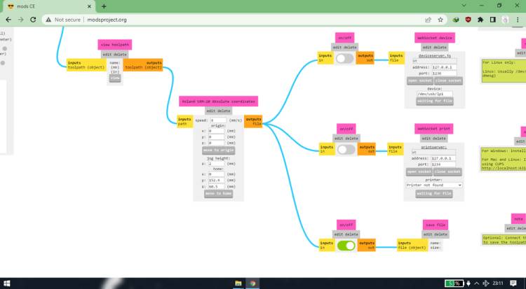
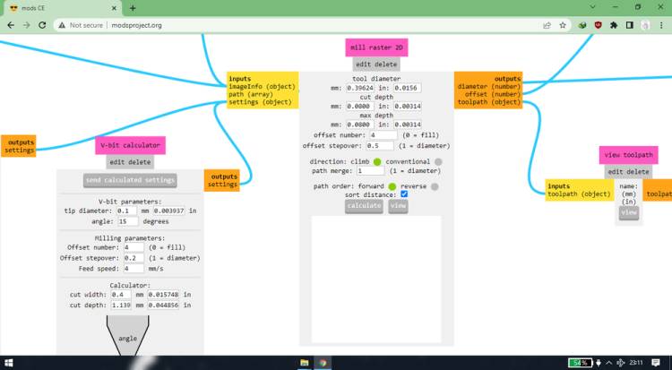
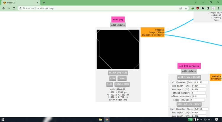
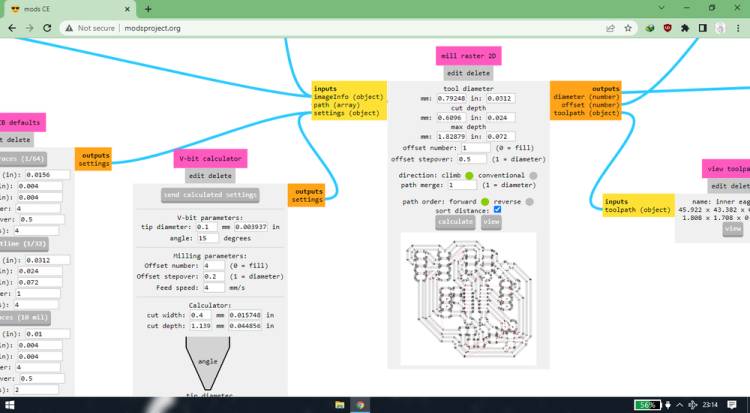
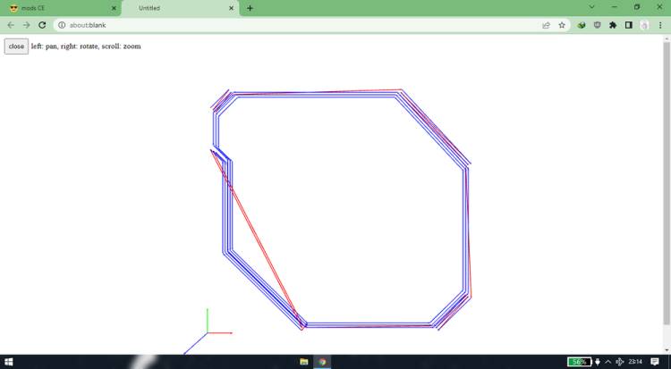
These are the mod settings i used to generate the toolpath/rml file,
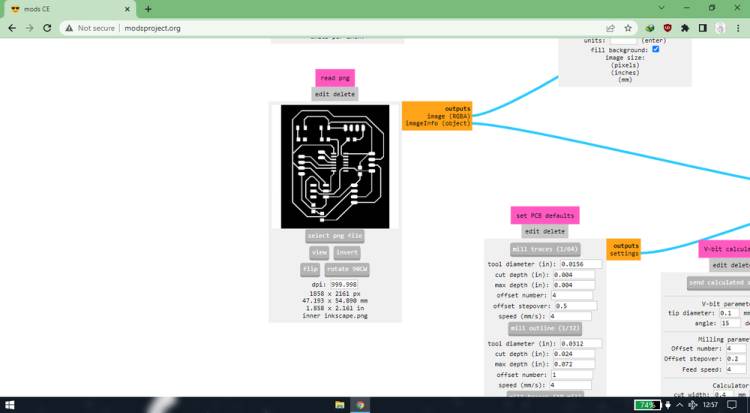
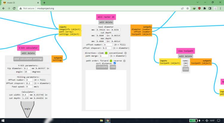
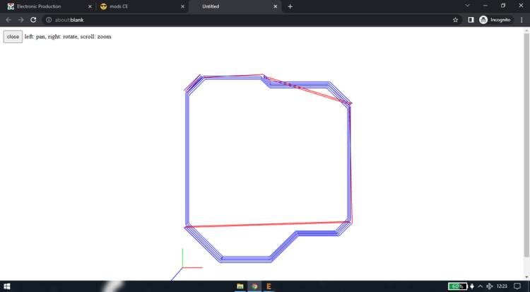
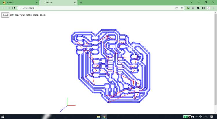
When i saw the generated toolpath for the outline, i saw that it was cutting extra border at few places,
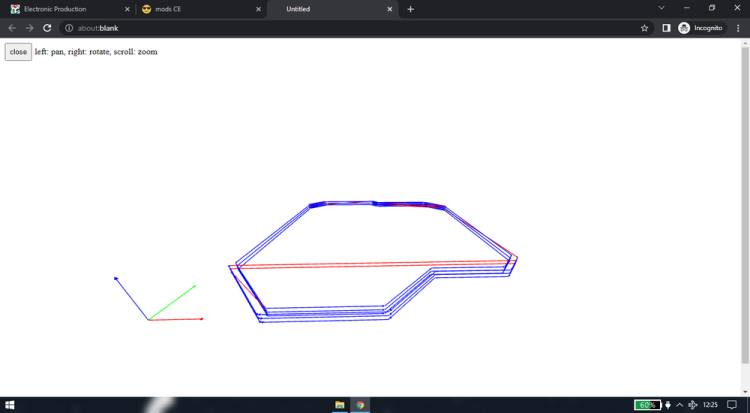
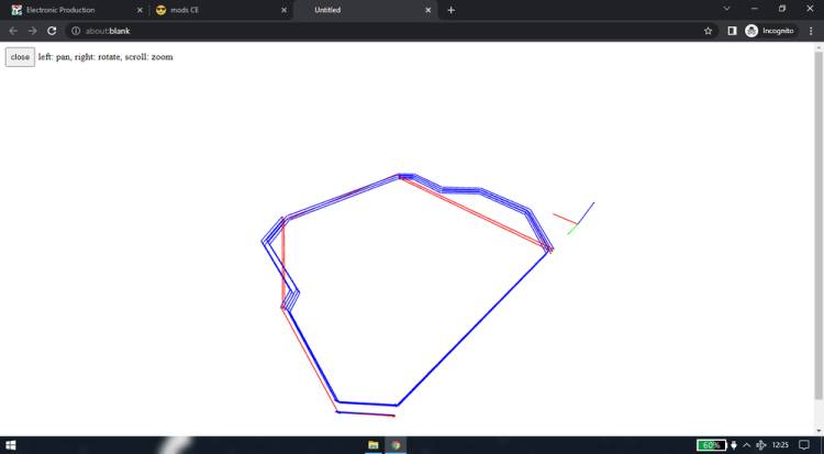
I tried tweaking few settings to see if the error goes, but i was getting the same result.
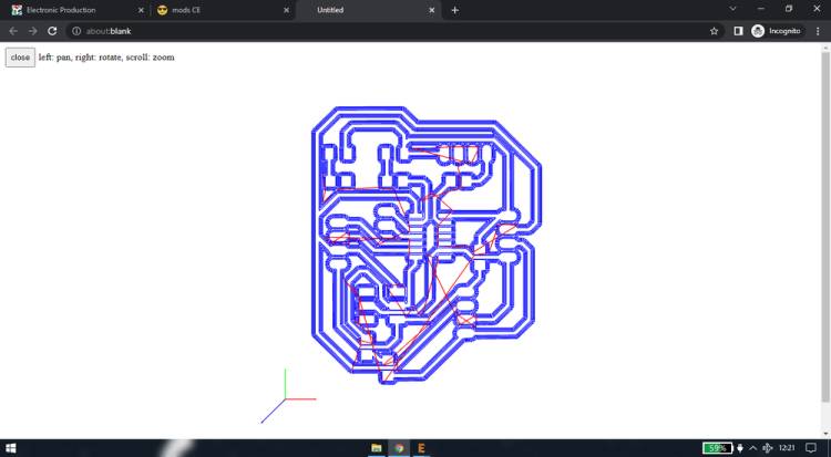
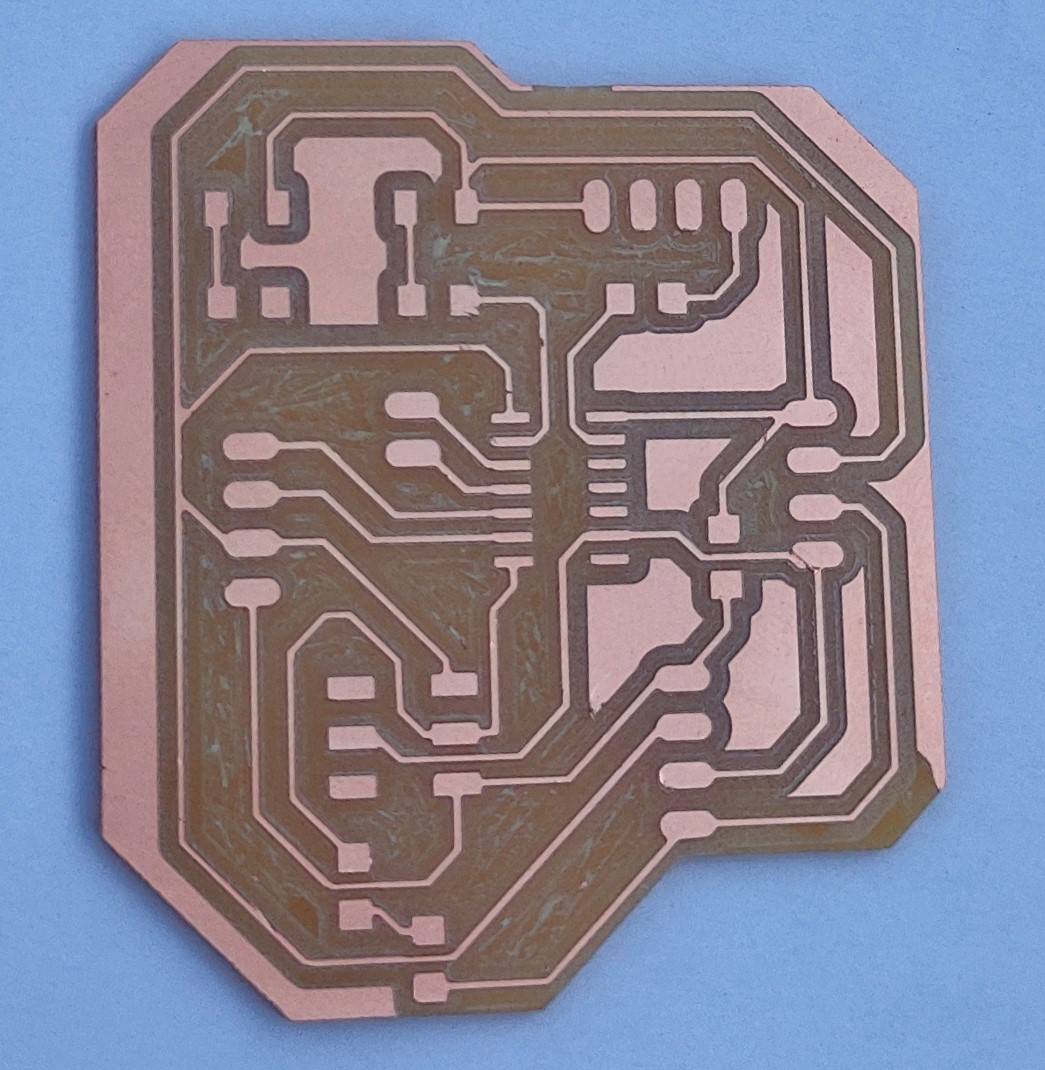
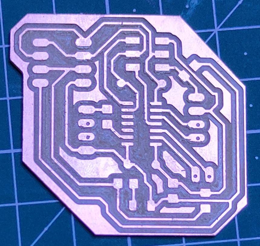
I then started milling the PCB. I used a VBIT whose tip was already broken previously. This is the trace i got(after a bit of cleaning),
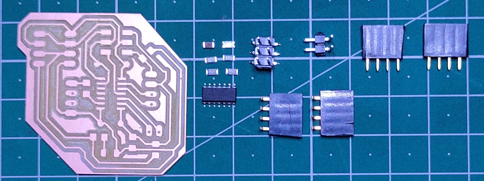
These are the components I used for the PCB,
2x female header pin(flat)
2x female header pin(90°)
2x male header pin
Attiny44
2x LED
3x 100ohms resistor
3x 0ohms resistor
after solder the IC and 2 LED,
My colleague was asking me about the wiring of the MISO/MOSI pin in the output board that is to be connected with the fabISP while he was routing
his output device board, it was then that i realised that i didn't give 2 connection for the fabISP connector in the output board. I don't know
why i did that, only connected 4 pins that was required and forgot to connect the other 2 pin. I also realised that i didn't add the capacitor.
So i then added the capacitor and re-rout the whole design, this was the final schematic and board,
Before re-routing, i should have checked the my hello world board that i designed previously, that way i would have realised that i forgot to
add a resonator in the PCB! And this time i had to use 2x 0ohms resistor that acted as a jumper,
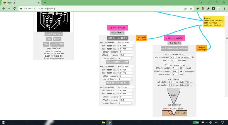
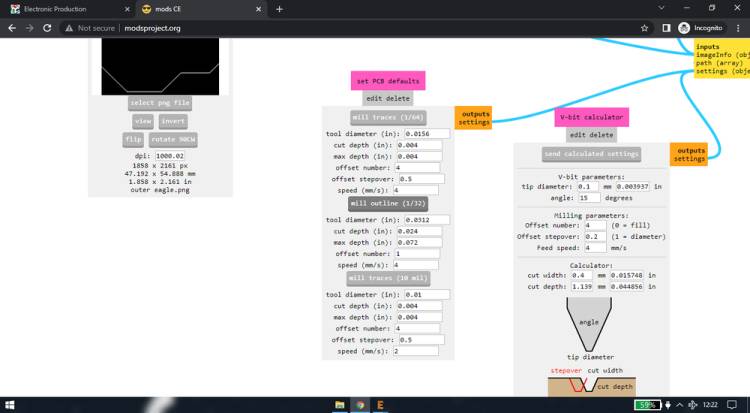
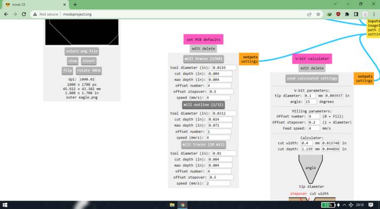
and this was the settings i used for generating the toolpath/rml file for the trace and cutting,
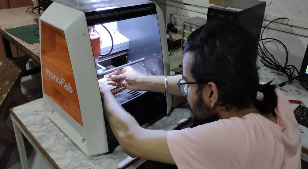
Milling the output board
This time too i used the VBIT, another broken one (So the thing with the vbit we are using is that the tip of the vbit is very thin, so it is
bound to broken no matter what. So all we need to take care of is that a very tiny bit of the vbit gets broken. And for the same reason, instead
of using the default setting in mods, i am using 0.0800 as cut depth and max depth, so the vbit doesn't go too deep inside the copper clad.
so in a nutshell, a fresh vbit is bound to breake 1-2 times so we need to take care that very minimal amout gets broken, and after vbit breaks
1-2 times, it will give you a fine finish just like 1/64 endmill)
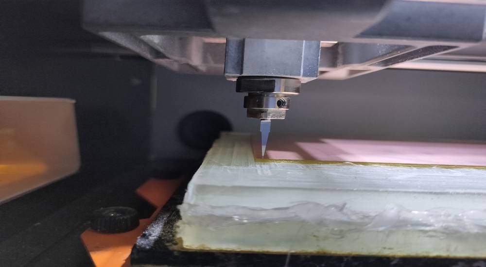
this is the outcome of the milling,
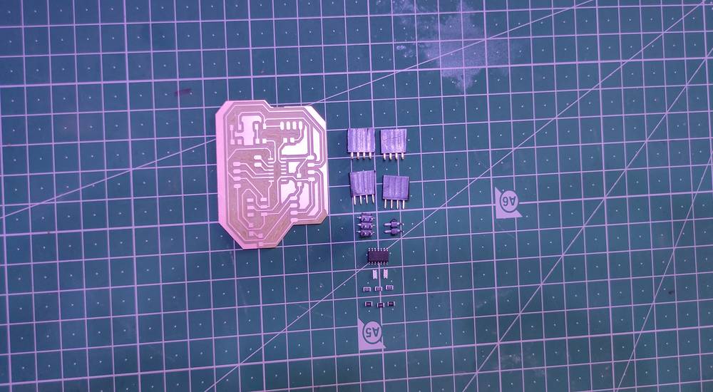
and these are the components i used,
Attiny44
2x 0ohms resistor
3x 100ohms resistor
1x 1 microfarad capacitor
2x female header pin(flat)
2x female header pin(90°)
2x male header pin
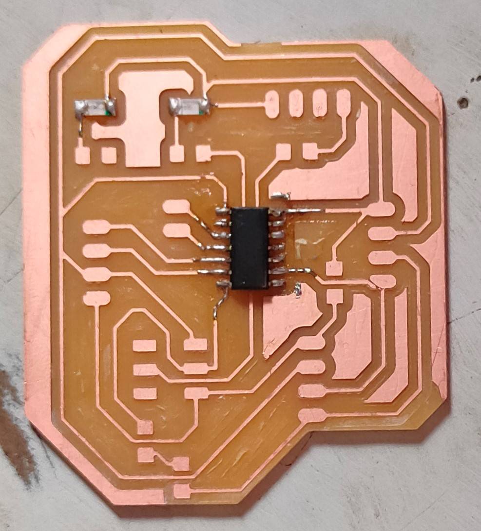
once the components were sorted, i started soldering,
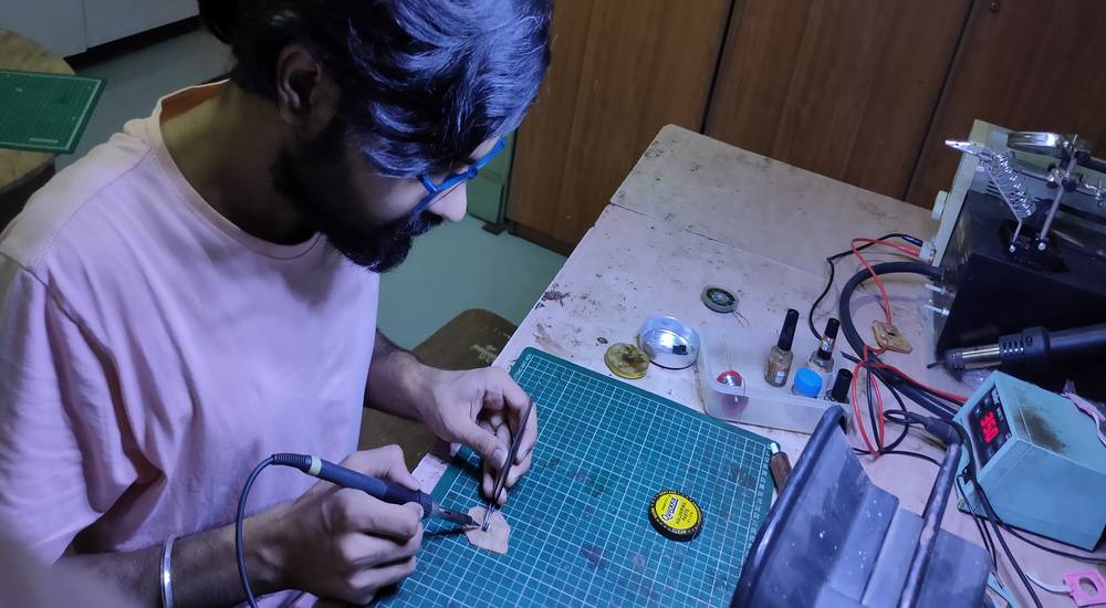
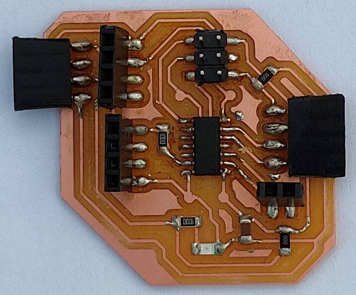
FInally the output board was ready(without resonator),
Programming the output board
The four header pin on the right was dedicated for the 7 segment display. The four header pin on the left was dedicated for the buzzer. On the
top left there are 2 header pins, left one was for lcd and the right one was for OLED. You can see the placement of component here,
while testing the output board, the 7 segment display was not working. SO i tried checking the connectivity, and it seemed fine. Then i checked
each and every pin by turning it high and putting a buzzer on the said pin when it was high, and it turned out that the PB8 pin of the IC was
not working!
Since 7 segment display can be operated by any 2 digital pin and VCC&GND i tried using the slot for the LCD and it worked fine, more on that later.
I tried using the OLED, LCD and 7 segment display to test the output board.
<<<---OLED--->>>
I was not even able to uplaod the sketch of the OLED_text to the output board.
<<<---LCD--->>>
Unlike the OLED, i was able to successfully upload the sketch however nothing was displaying on the LCD.
<<<---7 SEGMENT--->>>
As mentioned above, 1 out of 4 pin that was dedicated for the 7 segment was not working so instead i used the slot that was dedicated for the
LCD. I was using the same code as i had used for running 7 segment with UNO.
With the 7 segment connected to the output board and output board connected with fabISP, i observed that the green light in the fabISP, which
usually lit up when the code is being uploaded, was constantly stable and also there was an error while uplaoding the code.
when i removed the 7 segment, the green light turned off and i was even able to sucessfully upload the sketch.
After the code was uploaded, when i connected the 7 segment, it was still not displaying anything. After a while, i thought there might be some
issue with the power supply because of the USB extension i was using. So thn i tried to power the output board with the arduino which
can supply 5V of power and after powering the output board with 5V, it started displaying the digits.
here is an exception where the the 7 segment was displaying digit without any external power supply,
I then changed the slot of 7 segment from the header pin decdicated to LCD to the header pin dedicated to OLED. Same like before, when i connected
the 7 segment, the green light of the fabISP was constantly lit, but unlike the header pin dedicated to the LCD, i was able to uplaod the sketch
without first removing the 7 segment and also i didn't need to power the output board with external power supply, when i connected the 7 segment
to the header pin dedicated to the OLED.
You can see all the outcomes of the description that was mentioned above,
In this week i exlplored a lot of output devices like LED-buzzer, LCD, OLED, 7 segmen, Servo motor and stepper motor. I learned how to control
the devices with the arduino UNO by making modifications in the code and how to give connections to operate them. After learning how to operate
those devices on UNO and how to give the connections, i applied the same principles while making the output board with attiny44 IC. After i
designed and fabricated the output board, i found out that i was not even able to compile the sketch of OLED for the output booard. Then i found
out that the LCD too was not working with the output board. Then i tried the 7 segment display with the output board with same connections and
code and it seem to work. There were some power supply issue, which i solved by supplying the power externally. You'll find all the details above.
You can download the board file of output device from here:
output board
Group assignment
In the group assignment we measured the power consumption of the DC motor and RGB LED. You'll find it's documentation here:
https://fabacademy.org/2022/labs/vigyanashram/groupassig/groupassignment8.html
Drip Irritation by Fenil Chandarana is licensed under Attribution-NonCommercial-NoDerivatives 4.0 International![]()
![]()
![]()
![]()